What is post tensioning?
Post tensioning is a technique for reinforcing concrete. Post-tensioning is a method of applying compression after pouring concrete. Galvanised duct which is profiled using bar chairs follows the area where otherwise tension would occur in the concrete element. Steel strand (12.7mm typically) is pushed through the duct (known as tendons) and the concrete is poured. Once the concrete has achieved required strength, the tendons are stressed by hydraulic jacks. 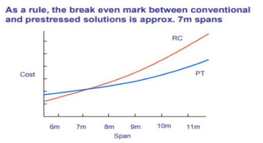 When the tendons have extended to the design specifications, they are wedged in position to maintain tension after the jacks are removed. The duct is then grouted to provide corrosion protection and to bond the strand to the concrete members.
Advantages of post-tensioning :
Longer SpansIt lets us design longer spans in elevated members, like floors or beams. Longer spans can be used reducing the number of columns. This results in larger, column free floor areas which greatly increase the flexibility of use for the structure and can result in higher rental returns.
Overall Structural CostThe total cost of materials, labour and formwork required to construct a floor is reduced for spans greater than 7 metres, thereby providing superior economy.
Eliminates shrinkages and cracksIt reduces or eliminates shrinkage cracking-therefore no joints, or fewer joints, are needed. Cracks that do form are held tightly together.
Reduced Floor to Floor HeightFor the same imposed load, thinner slabs can be used. The reduced section depths allow minimum building height with resultant savings in facade costs. Alternatively, for taller buildings it can allow more floors to be constructed within the original building envelope.
Deflection Free SlabsUndesirable deflections under service loads can be virtually eliminated.
Waterproof SlabsPost-tensioned slabs can be designed to be crack free and therefore waterproof slabs are possible. Achievement of this objective depends upon careful design, detailing and construction. The choice of concrete mix and curing methods along with quality workmanship also play a key role.
Early Formwork StrippingThe earlier stripping of formwork and reduced back propping requirements enable faster construction cycles and quick re-use of formwork. This increase in speed of construction is explained further in the next section on economics.
Materials HandlingThe reduced material quantities in concrete and reinforcement greatly benefit on-site cranage requirements. The strength of post-tensioning strand is approximately 4 times that of conventional reinforcement. Therefore the total weight of reinforcing material is greatly reduced.
Column and Footing DesignThe reduced floor dead loads may be utilised in more economical design of the reinforced concrete columns and footings. In multi-storey buildings, reduced column sizes may increase the floor net area.
Soil typeIt allows us to build slabs on expansive or soft soils.
Applications for PT
Slabs on ground: Today, PT is used extensively for slabs on grade where soils are likely to move (expansive soils).
Another good application for PT slabs is producing crack-free tennis courts.
A recently developed application of PT is external post-tensioning for strengthening of existing structures, especially as an upgrade to resist seismic forces.
Bridge designers have used PT both for cast-in-place concrete and for precast segmental construction as PT allows longer spans and keeps cracks tight.
Concrete water tanks are often post-tensioned to reduce crack width and leakage.
Masonry walls can be post-tensioned-this is usually done with a solid steel bar fastened to the foundation and stressed with a nut at the wall's top.
One interesting application is for a concrete countertop that needed to span 6 feet and carry a heavy load.
Why should I be interested in post-tensioning?
The advantage of post-tensioning is flexibility of design, allows to build on expansive soil, low material cost, reduces the amount of ground works required. It also reduces maintenance costs and also will be able to increase the future loading. Thinner PT slabs and early strength stressing gives a faster floor cycle time, allowing the structure to progress fastly It is used for bridges and stadiums where there are complex curves, elevations and grade changes. In stadiums, post-tensioning allows long clear spans and a highly creative architectural approach. In commercial buildings space and light can be maximized by construction of large column-free spaces. PT will need fewer joints and thus reduced joint maintenance and helps to increase durability. In tanks and silos post-tensioning can provide crack-free concrete.
Post Tensioning Benefits for Contractors
Post-tensioning has the potential to lead the way in the building industry in the India. It brings huge savings to the cost of construction and therefore there has been a steady growth in the number of installers. Post-tensioning brings benefits to both contractor and developer alike:
Reduced Costs through reduced quantities of rebar and concrete.
Reduced cladding costs through control of deflection and reduced storey height.
Significant benefits in the speed of construction make post-tensioning ideally suited to accelerated construction schedules. The reduction in the amount of material required and the subsequent reduced reinforcement congestion, allow the fixing of the systems and the placing of the concrete to be achieved more quickly and easily. Post-tensioning also allows early stripping of formwork, accelerating floor construction.
PT slabs are thinner than reinforced concrete slabs and so a larger area can be poured for the same volume of concrete. Large area pours reduce the number of pours and increase construction speed and efficiency.
Less materials equals reduced storage on site, and also means less crane time is required for the slab construction, and more crane time can be afforded to other elements of the structures construction.
Slabs with fewer or no expansion joints.
Skilled and professional labour from STRANDS contractors.
The amount of concrete used in a post-tensioned concrete slab can be up to 30% less than that required in traditional reinforced concrete. This can lead to reduced embodied energy and carbon emission, fewer deliveries to site also contribute.
Mechanical and electrical services are an expensive and programme-critical element in construction, with significant maintenance and replacement issues, STRANDS contractors can often quote an additional cost for horizontal services distribution below a profiled slab, of up to 15%. PT concrete floors generally have a flat soffit which provides a zone for services distribution free of any down-stand beams. This reduces design team coordination effort and risk of errors. It also allows flexibility in design and adaptability in use. A flat soffit permits maximum off-site fabrication of services, higher quality work and quicker installation.
Inherent fire resistance means concrete structures generally do not require additional fire protection. This reduces time, costs, use of a separate trade and ongoing maintenance for applied fire protection.
Part L of the Building Regulations requires pre-completion pressure testing. Failing these tests means a time consuming process of inspecting joints and interfaces, resealing where necessary. Concrete edge details are simpler to seal, with less failure risk.
Sealing and fire stopping at partition heads is simplest with flat soffits. Significant savings of up to 10% of the partitions package can be made compared to the equivalent dry lining package abutting a profiled soffit with down-stands. This can represent up to 4% of the frame cost, and a significant reduction in programme length.
PROCESS FLOW OF PROJECT
It starts with a discussionWhen you get in touch with STRANDS,our personnel will visits you to discuss and understand the requirements of the project. This information will be used for the further process.
The following are the processes which undergoes till the final execution at site.
Over to STRANDSOnce your drawings reach us, we create a database keeping all your requirements in mind. We try to make feasible and best solution that meets your requirements as fast as we can.
Feasibility checkThrough our experiences gained from different variety of projects, we have determined to deliver quick, quality and best solutions. We understand the importance of the customer requirements. That is why we have committed ourselves to bring out the best feasible outcome for our customers.
Prelim design and EstimationAs soon feasibility is checked, we prepare a preliminary design based on the structural configuration and feasibility.This inputs are used to derive the quantity estimation for PT Elements and other items.
Final design for constructionSTRANDS uses the latest design software which is continually updated to reflect current national and international construction codes of practice. STRANDS prepares a set of drawings like forming plan, reinforcement plan and PT drawings. This set of drawings are send to the site for further implementation of the system.
Product assemblingSTRANDS delivers outstanding post-tensioning solutions and products. The drawing displays the layout of PT cable and its accessories.This give the details of the BOQ and based on this, the final product is prepared for the respective project.
On site activitiesSTRANDS keeps the safety on site as one of the top priority. STRANDS is committed to maintain its quality both in design and at site. The installation and stressing activities at project site are followed by number of inspection and quality assurance formalities.
Final reviewSTRANDS assures its clients by issuing a Certificate of Stability after conducting gravity analysis and design of PT. This will affirm the stability and quality of the PT members to provide intended function under the gravity condition.
General Criteria for the Design of Post-Tensioned Elements
(Ref.: ACI 318M-11, IS 1343 : 2012, IS 456 : 2000 and Post-Tensioning Manual, 6th Edition)
- Live Load (LL): in kN/m2 (As per recommendation received from the Structural Consultant)
- Floor Finish (FF): in kN/m2 (As per recommendation received from the Structural Consultant)
- Wall Load: in kN/m2 (either as per recommendation of the Structural consultant or as per the information available about the wall layout, thickness and unit weight of the material to be used)
- Service Duct & False Ceiling Load: in kN/m2 (As per recommendation received from the Structural Consultant)
- Self-weight of the members: as per the section size (considering pre-stressed concrete weight 23.5 kN/m3 as per IS 875 part 1 : 1987)
- Minimum Grade of Concrete (fck): M35 (cube strength)
- Grade of Steel: fe415 or fe500 (as per the recommendation from the consultant/client in advance for the prelim design)
- Level of Prestressing as per ACI 318M-11 (clause 18.3.3):
- For Two-Way Flat Slabs: Class U; Tensile Stress Limit of concrete slab section for "Serviceability Design Requirements as per ACI 318": less than or equal to 0.5*square root of equivalent cylindrical strength value of concrete grade at the mid-span bottom fiber zone.
- For One-Way Slabs and Beams: Class T for the Normal Loading Criteria and Class C for heavy loads from floating (stub) column to the Girders as well as for member design for Fire Tender Loading.
- Level of Prestressing as per IS 1343-2012 (clause 24.2.1):
- For Two-Way Flat Slabs: Type-2 with tensile stresses below 3N/mm2 at the mid-span bottom fiber zone.
- For One-Way Slabs and Beams: Type-2 for the Normal Loading Criteria, and Type-3 for heavy loads from floating (stub) column to the Girders as well as for member design for Fire Tender Loading.
- Criteria for maximum spacing of tendon placement shall be followed as per ACI 318M-11 clause 18.12.4: 8*slab thickness and 5ft whichever is smaller for the uniformly distributed tendons in slab.
- Additional non-prestressed reinforcement provided as per the criteria of ACI 318M-11 clause 18.9 for minimum non-prestressed reinforcement and clause 18.7 for the required non-prestressed reinforcement to achieve required flexural strength at ultimate load combination case. Reinforcement requirement for temperature and shrinkage effects shall be as per clause 19.6.3.3 of IS 1343 : 2012 i.e. 0.15% of total cross section area of the concrete section.
- Permissible Deflection values (Long Term with shrinkage and creep effect considering creep coefficient as 2) as per IS 1343 : 2012 clause: 20.3.1 a, b, c:
- Final Downward Deflection due to SW + LL + FF + SDL + PT + Effects of Shrinkage and Creep (corresponding to SW + FF + SDL + PT) should not be more than span/250
- Downward Deflection (occurring after erection of partitions and the application of finishes) due to Shrinkage and Creep (corresponding to SW + FF + SDL + PT) and LL should not be more than span/350 or 20mm whichever is lesser shall be considered.
- Total upward deflection should not exceed span/300 unless uniformity of camber between adjacent units ca be ensured. Note: The criteria 12.1 and 12.2 same as prescribed in IS 456 : 2000 clause 23.2.a and 23.2.b respectively.
- Anchorage of PT Cable shall be placed such that the centroid of all the anchorage should fall under middle-third of the depth (kern) of member. Preferably, it shall not be more than 2/3 depth of the member when measured from the bottom.
- The minimum CGS height of tendon at the mid-span shall not be less than 38 mm in case of slab and 55mm in case of beam when measured from the bottom.
- Minimum clear cover to the reinforcement shall be 20 mm for the slab and 35 mm clear from the longitudinal reinforcement for the beams.
- STRANDS submits moment of resistance (moment capacity) at respective sections for PT beams when the Structural Consultant likes to consider them for the lateral force resisting system. The Consultant can provide necessary passive reinforcement based on the moment of resistance in addition to the requirements of gravity force design performed at STRANDS.
IS 456 : 2000 Indian Standard Plain and Reinforced Concrete – Code of Practice
Published by: Bureau of Indian Standards, New Delhi, India
This standard deals with the general structural use of plain and reinforced concrete. It provides guidelines about the material used in building construction such as cement, mineral admixtures, aggregates, water, chemical admixtures, reinforcement, concrete, etc. In addition to this, general design considerations such as stability of structures, serviceability aspects, fire resistance, durability, workmanship, reinforcement detailing for various structural elements and general criteria for the arrangement of reinforcement to achieve necessary workmanship are prescribed.
Published by: Bureau of Indian Standards, New Delhi, India
This standard deals with the general structural use of prestressed concrete. It covers both work carried out on site and the manufacture of precast prestressed concrete units. It describes about materials, workmanship, its inspection and testing, general design requirements, structural design based on limit state method. There are three classifications described under the serviceability aspects based on the amount (level) of prestressing; such as type 1, 2 and 3. The major revision was in the direction of activities related to grouting that are carried out after stressing of tendons in bonded (grouted) PT system. All the provisions are mainly for prestressed beams and girders. Provisions for post tensioning in slab are not been incorporated.
Published by: Bureau of Indian Standards, New Delhi, India
This standard covers the requirements for designing and detailing of monolithic reinforced concrete buildings so as to resist severe earthquake shocks without collapse.
Published by: Bureau of Indian Standards, New Delhi, India
This standard guides for the consideration of loading during the design of structural members. The minimum requirements pertaining to the structural safety buildings are being covered in this code by way of laying down minimum design loads which have to be assumed for dead loads, imposed loads, wind loads, snow loads and other external loads, the structure would be required to bear. We follow this document in absence of the loading criteria - generally recommended by Structural Consultant of the project.
Published by: Bureau of Indian Standards, New Delhi, India
This standard covers the requirements for manufacture, supply and testing of un-coated, stress relieved low relaxation seven-ply steel strands for prestressed concrete.
Published by: Bureau of Indian Standards, New Delhi, India
This standard covers grades and the requirements of iron casting with spheroidal or nodular graphite classified on the basis of mechanical properties measured on test pieces prepared from separately-cast test samples, and from cast-on test samples.
Published by: Bureau of Indian Standards, New Delhi, India
This standard covers the mechanical properties, hardenability and isothermal transformation characteristics of 20MnCr5 grade of steel for use by automobile and ancillary industry.
Published by: American Concrete Institute, USA
This Code covers the materials, design, and construction of structural concrete used in buildings and where applicable in non-building structures. The Code also covers the strength evaluation of existing concrete structures. Among the subjects covered are: contract documents; inspection; materials; durability requirements; Concrete quality; reinforcement details; analysis and design; strength and serviceability; precast concrete; prestressed concrete; strength evaluation of existing structures; and provisions for seismic design. The commentary is provided to mention the considerations of the committee in developing the criteria. Here, in chapter 18, which is exclusively for Prestressed Concrete, all the aspects related to unbonded post-tensioned system are nicely described which includes criteria for PT slab as well as PT beams. This also classifies the level of prestressing in terms of class U, T and C based on the tensile stresses permitted in the tension zones of PT element.
Published by: American Concrete Institute, USA
These specifications provide specific performance criteria for materials for unbonded single strand tendons and detailed recommendations for fabrication and installation of unbonded single strand tendons.
Published by: Post Tensioning Institute, AZ, USA
These specifications provide specific performance criteria for materials for unbonded single strand tendons and detailed recommendations for fabrication and installation of unbonded single strand tendons.
Value Engineering
Our employees have gained experience and proficiency from variety of projects across all over India. STRANDS' employees are able to bring out the latest ideas and have the skills to work on different new technologies from market. Using value engineering methodology, STRANDS can determine the most advantageous to meet the specific requirements of a customer.
Working StandardsSTRANDS have resolute, professional engineers having in-depth knowledge of reinforced and pre-stressed concrete and possess a considerable understanding of the design of structures.
DesigningAt STRANDS, designing is done to create safe, refined, durable , cost-effective structures which are also sustainability. We believe in maintaining the designing standards and always try to provide the requirement of the customer.
DrawingThe detailing of specific elements are provided in the form of drawings along with the design .We implement graphical representation of the elements, so that it can be easily understood and grasped by site engineers and contractors.
OperationsSTRANDS strictly follows the guidelines specified in the "Field Procedures Manual for Unbonded Single Strand Tendons", 3rd Edition, Post-Tensioning Institute. With adherence to that our team conducts inspection after every cycle of installation and stressing activity respectively. The inspection reports are regularly reviewed and necessary steps are taken accordingly.
Construction Methodology
Scope of Work for Mono-strand Unbonded Post-Tensioning System
- Formwork shall be made (by general contractor) as per the forming plan issued by STRANDS / Structural Consultant. There is nothing special except the wooden sides (shall be provided by general contractor) required for drilling holes (by STRANDS) so that the cables can be passed through them at required places at certain height as per PT detail.
- Do not provide camber to any of the PT elements (PT slab or PT beam) without prior consent to STRANDS.
- In case of PT beam, the steel cage (i.e. open stirrups near the supports up to 2m and closed stirrups in mid-span zone with continuous longitudinal steel only) is prepared (by general contractor) as per regular practice with the detail provided. Do not place extra top steel at this time.
- Support bars are fixed (by STRANDS) at certain intervals and heights as per PT drawing.
- PT cable to be placed over the support bars in PT beam (by STRANDS).
- The wooden sides of PT beam or PT slab are marked and drilled (by STRANDS) at specific places. Anchorage assembly is fixed at the wooden side (by STRANDS). The side is then fixed up to its place (by general contractor) after or before installation of cable (as per site condition).
- Cable is passed through the assembly and the extra length kept beyond the side for stressing wherever required as per drawing (by STRANDS).
- After installation of PT Cables, extra top steel shall be placed (by general contractor) in PT beam and PT slab as per drawing.
- After installation of PT Cables, Concealed conduits for electrical purpose must be placed (by Electrical Agency). ANY KIND OF ALTERATION IN PT CABLES ARE STRICTLY PROHIBITED while placing electrical conduits if there is any.
- Final checking of the PT system by the engineer of STRANDS on site. It is recommended that the steel detail got checked on site by the engineer from the Structural Consultant as well.
- Concrete must be well compacted especially at surrounding of the anchorages as well as in remaining area with due care (RMC / Concrete Agency).
- Cubes are cast on site (by RMC / Concrete Agency) for 5 day and 28 day strength testing as per respective codal provisions. Certain cubes required to test (by other agency) between 5 to 7 days depending on the commitment of strength gain by the concrete supplier in accordance with respective codal provisions.
- Stressing is commenced (by STRANDS) once the target strength for stressing (25MPa) is ensured through the cube testing.
- Stressing is performed as per stressing sequence already provided to the stressing personnel. Stressing platforms must be ready on site as well as electricity supply must be arranged on the floor (by general contractor) prior to stressing.
- Elongations are measured on site; Stressing Record is generated (by STRANDS) for our internal approval. Post stressing status is conveyed to the Structural Consultant, General Contractor, PMC and Owner for shuttering removal (by STRANDS). Elongation Report is sent (by STRANDS) to the Structural Consultant for his reference.
- Shuttering can be started (by general contractor) for the successive floor above.
- Sufficient propping (re-shoring) shall be provided (by general contractor) to the floor(s) up to one or more levels down (based on the mass of the wet concrete according to the thickness of PT slab + size of PT beam) on which this form-work is resting. Re-shoring below the lower floor shall be removed only after getting approval of de-shuttering (removal of shuttering) for the successive (above) floor through email from STRANDS.